|
|
|
|
|
As usual, click an image for a larger view. What have I got? This is
a relatively standard domestic indirect hot water tank with a 28mm
indirect coil. I'm planning on having several heat generating sources in the future. At the moment the hot water tank is only heated by electric. I 'used' to have a LPG boiler running off a bulk tank in the garden, but that was ridiculously expensive to run, so the LPG system was removed. I've always wanted the HWT to be heated off the wood burning stove, but I'd have to take the house to bits to install the pipework and the HWT and WBS were at opposite ends of the house, so the two were never connected. Time has now moved on and I am room by room gutting them to install thick layers of insulation which has made a massive difference to the warmth of the property, let alone cutting our use of wood fuel by around two thirds. I have covered the pipework between the WBS and the HWT in the Wood Burning Stove - Flue Heat Recovery pages.
Coming back to this tank... Present and
future heat sources will be wood burning stove, thermal solar panels, air
source heat pump and obviously the emersion heater. Looking around there
are many fancy ways to connect various heat sources with loads of
different control systems, but no one seemed to have any definitive ways
to connect all sources, especially as I would need different solutions/liquids in
each system (anti-freeze, Fernox), so I got thinking and came up with the
idea of modifying my HWT to have several direct heat exchangers built in
to and on the tank. Many have suggested using external plate heat
exchangers, but I felt I'd have a lot of un-necessary pipework and pumps
that way, plus some loss of heat transfer efficiency, hence my experiment
of modifying the tank to have a number of separate indirect heat transfer
systems. |
 View showing the secondary coil connections (internal heat exchanger) |
 |
 Using a wire brush cup attachment in an angle grinder I cleaned up the copper. |
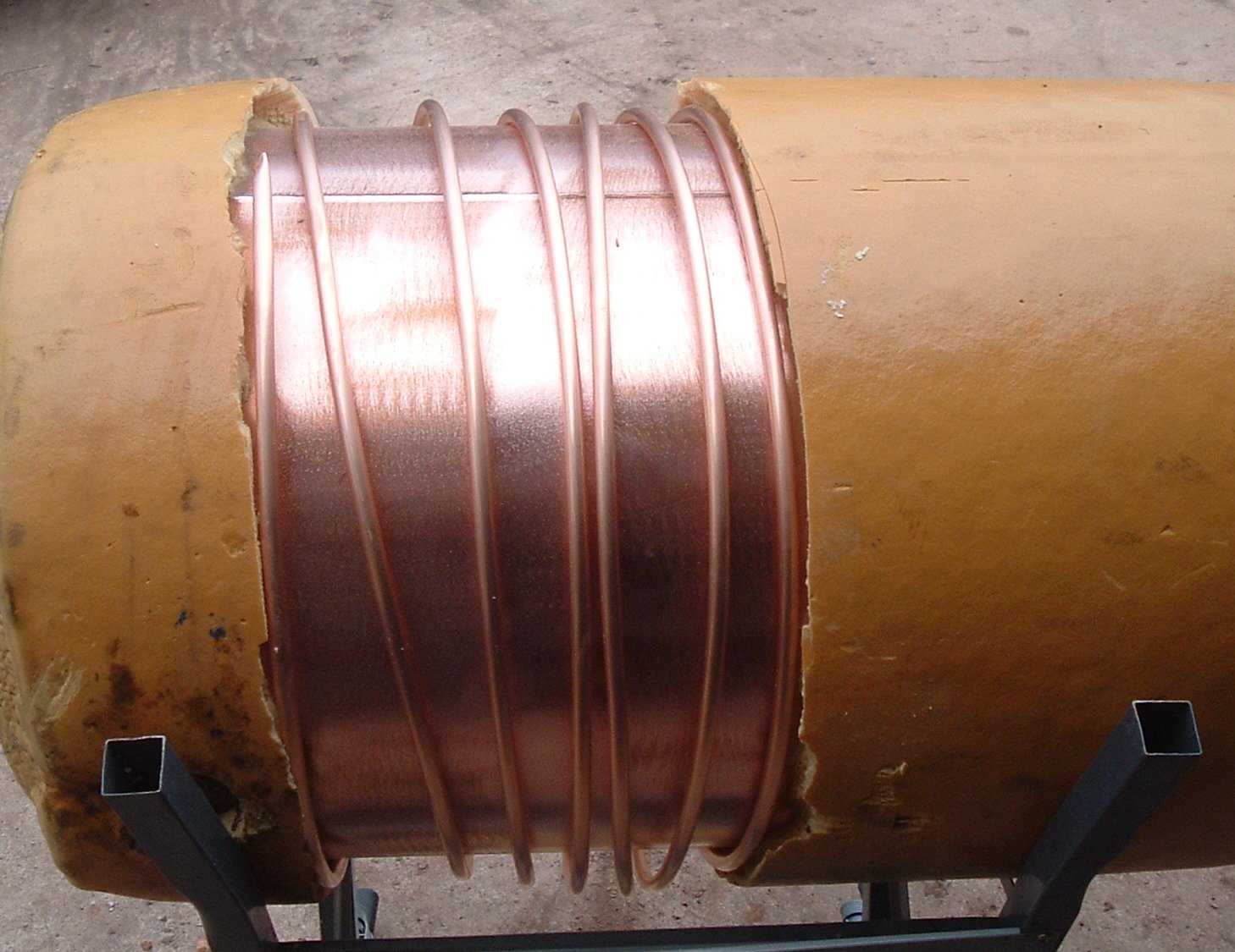 The pipe I used is 10mm microbore and is supplied in 10 meter coiled lengths. Rather than openening up the coil, only to have to re-wrap it around the tank, I carefully opened up the coil enough to pass it over the end of the tank, thus little dressing was required. When in position I liberally brushed on some Laco flux. The tank is sat in an up-side down work-mate type thing to make it easier to work on. |
 The way I worked was to initially solder the end to the tank (getting my mate with a bit of wood to hold in position), then starting about a foot away from the last soldering, holding with wood, check the pipe was in contact with the tank and dressing with a soft mallet where required, I'd start heating by the wood, then when up to temperature follow the flame with the solder up to the last section. When I had soldered the pipe in place, I then ran another run of solder on the other side of the pipe. BTW I brushed extra flux on for every section. |
 This is the coil after a good wash to remove any excess flux. The solder has gone a bit black, probably because I didn't wash off the tank until 3 days later. |
 The ends of the microbore before joining them in to two in to one manifolds |
While I was in an experimental mood, I thought I'd have a go at fitting an
internal coil of 10mm microbore... My microbore coil after being wound around a 6" pipe/former |
 |
 I drilled a suitable hole top and bottom of the tank to fit some modified tank connectors where I had removed the shoulder to allow the 10mm to slide through the tank connector. It was a shame it was not possible to easily fit the nice uniform coil in through the emersion heater port, as it looks quite neat. To get the coil in through the port, I had to expand it slightly to enable me to wind (screw) the coil down through the port, then it was the tricky bit of getting the bottom of the coil to come out of the bottom hole which was finally achieved by first adding a bit of wire to use as a fish to the bottom of the coil, then out through the bottom port. Got there in the end! |
 Okay, not a brilliant photo, but its a view through the emersion heater port with the new coil in place. |
 Just a quick photo of the top and bottom ports for the internal coil. |
 Just showing three short bits of 10mm to act as pockets for thermocouples. I later re-soldered them to face upwards so that I could add a drop of thermal liquid to help the thermocouples read more accurately. |
